Options
The following options and kits represent only those most commonly requested by FSI's customers. FSI also provide more specialist kits for a variety of uses and have a number of partner organisations who can meet a wide range of requirements. Customers requiring any modifications not listed here should contact FSI for further information. Customers should note however that FSI do not supply military hardware or fittings for their Rotons. Military customers should contact one of FSI's licencees (list available on application) who produce a wide range of Rotons (either modified versions of FSI models or custom designs) for military applications.
Construction Options
The following options are normally only available if specified at the time of ordering as they require changes to the internal structure of the Roton during construction. Modifications which provide similar facilities can of course be retro fitted but the use of space and vehicle performance can be significantly degraded.
Any of the construction options can be specified for later implementation in which case the appropriate changes are made to the Roton's structure but the additional equipment is not installed. Thus in the case of passenger facilities the required support points for the internal passenger cabin and interfaces to power supplies etc would be provided but the cabin itself would not be installed. In these cases the required modifications typically take up 5% of the final volume/mass requirement but allow the retro fitting of the option at some later date.
Cargo & Passenger Facilities
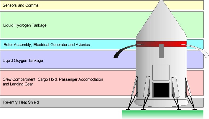
The basic FSI Roton's are supplied with an unpressurised cargo bay however it is possible to subdivide the cargo bay during construction to provide a combination of passenger accomodation and cargo space. Typically each additional passenger requires 2.5 tonnes of cargo space to provide full life support facilities and standard class accomodation. Increasing the luxury of the accomodation increases the space requirements (business class typically 3.0 tonnes, first class 3.5 tonnes per passenger). The precise requirements depend upon the required layout and any additional faclities required (eg. sanitary facilities, catering etc.).
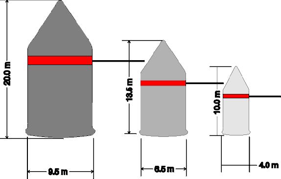
In the HL-90 and ML-95 models there is an additional 10 tonnes requirement for a separate passenger airlock (in the E-99 the passengers utilize the crew airlock).
Pressurised Cargo Bay
The cargo bay may be pressurised and fitted with a docking hatch to the OIN 101332-2266 standard. This provides a sealed entrance to the cargo bay but not an airlock facility.
Both the pressurised and non pressurised versions of the cargo hatch use a combined hinge and slider mechanism that pushes the door cover out and away from the main body and then upwards so that the cover is held vertically above the cargo bay entrance. This allows easy access for docking tubes with the minimum of interference from the cover. In the pressurised version the pressure door itself slides vertically upwards within the door frame above the entrance.
Control Options
All FSI's Rotons are supplied with both manual and automatic controls. If specifeid when ordereing however Rotons which are only required to operate under a fully controlled aerospace regime can be supplied with automatic controls only resulting in an additional 7 tonnes of payload.
Option Kits
All option kits can be fitted to Rotons either during original production or later either by FSI or by the customers own maintenance personnel.
Heavy Duty Landing Struts
The standard Roton landing struts are designed for use on prepared landing zones and require a flat, hard and solid surface to function correctly. The heavy duty struts are designed to cope with less ideal conditions and are capable of supporting a fully loaded Roton on rough terrain and slopes of up to 10% when the appropriate landing feet are used.
All Rotons are supplied with light weight landing pads designed to match the standard struts. FSI supply a number of alternative landing feet all of which require the use of heavy duty struts.
Wheeled Landing Gear
If landing on a prepared strip a Roton with wheeled landing gear can be rolled into position. Wheeled landing feet obviates the need for jacking the standard light weight pads thus reducing turn around times at busy airports. Note that the roton can only be safely rolled when empty of both fuel and cargo.
Heavy Duty Landing Pads
These pads are more robust and have larger surface areas than the standard light weight pads. They are also articulated to accomodate uneven landing surfaces. The use of heavy duty pads allows the Roton to land on unprepared landing sites provided that the ground is firm and the slope not more than 10% across the landing area. Heavy duty pads can be used with the standard wheeled jacks supplied with the Roton to allow ground movement.
Disposable Inflatable Landing Pads
In the event that the Roton is required to land on soft ground heavy duty landing pads can be fitted with inflatable pads which are inflated prior to touch down. The inflatable pads act to increase the load bearing area thus allowing the Roton to land on soft ground without sinking in. The pads are detached for lift off to prevent problems of ground adhesion and to avoid the need for complex recovery mechanisms.
Extended Duration Life Support
The standard Roton life support systems are simple low maintenance units albeit with a limited duration of 24 hours (48 hours on emergency settings). It is assumed that all life support functions will be provided by ground or obital facilities when the Roton is not in flight.
If longer duration life support is required (if for instance no ground based facilities are available and the local atmosphere is unbreathable) additional recycling and storage systems can be fitted to extend life support duration to one month between servicing and re-supply.
Internal Cargo Ramp
Where limited ground facilities are available an internal cargo ramp can be used to allow foot and vehicle access to the Roton cargo bay. The ramp module is housed by fitting a false floor in the cargo bay to provide the space for the ramp and its associated machinery.
When deployed the ramp can withstand loads of up to 100 tonnes and (assuming a flat landing ground) has a slope of 33%.
Internal Cargo Handling
The Roton cargo bay can be fitted with an electrically operated hoist and arm to facilitate the movement of cargo. The crane is fitted to the roof of the bay and allows the movement of cargo throughout the cargo space. The crane is remotely operated by a banksman within the cargo bay or by the flight engineet from the cockpit.
The internal cargo handling cannot move cargo out of the bay but is capable of loading vehicles present in the bay. The crane's maximum safe working load is 20 tonnes.
Cargo Airlock System (CAS)
For Roton's fitted with a pressurised cargo bay it may often be necessary to transfer cargo to vessels or facilities lacking the appropriate docking equipment. To meet this eventuality FSI supply a versatile cargo airock system (CAS). The CAS consists of a robust, double skinned, fabric tunnel supported by a combination folding strut / inflatable frame. One end of tunnel is attached to the cargo hatch while the other is fitted with an airtight door.
The CAS can be fitted either internally (within the cargo bay) or externally. If deployed externally in zero-G the CAS simply protrudes from the side of the Roton, on the ground the CAS can only be deployed externally in combination with the cargo ramp. The CAS can be deployed automatically in all three configurations provided that sufficient clear space and proper support is available. The CAS is sized to pass cargo up to 20% of total cargo capacity of the cargo bay but can be contracted to sizes down to 5%. If deployed within the cargo bay the CAS takes up the relevant cargo volume plus an additional 2% for the structure itself.
The CAS consists of four square inflatable frames (with each side of each frame being capable of being inflated or deflated independently). The corners of each frame are linked to the corners of the next by four inflatable horizontal beams thus the overall structure consists of three
All the CAS functions, apart from the Roton's pressure hatch, are operated by the compressed gas system used to inflate the structure. During deployment the structure is unfolded by light weight struts, the main supports are then inflated sequentially.
As the CAS can be fitted to any hatch conforming to the OIN 101332-2266 standard FSI also supply the system to non Roton users.
Deployable Cargo Crane
For cargo unloading, where ground facilities are limited, the Roton can be fitted with a support frame and motorised hoist capable of moving loads up to 20 tonnes from the cargo bay up to 15 metres from the cargo bay door (typically on to the load bed of a ground vehicle).
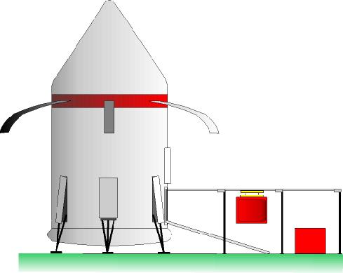
The frame consists of telescopic rail that extends from the top of cargo supported by legs at 5 metre intervals. The whole structure deploys automatically from the cargo bay door and is compatible with the Internal Cargo Handling System, Cargo Ramp and the Cargo Airlock System (CAS).
The Cargo Crane can be deployed automatically provided that a flat paved surface is available for the support legs however if no prepared surface is available, or there is a significant slope, manual assistance is required. The CAS / Crane combination can also be deployed automatically to produce an airlock structure through which cargo containers can be trasnported by crane.
It is not possible to combine the crane with both the CAS and the internal ramp unless the ramp can be deployed horizontally. FSI supply an optional kit for the internal ramp which allows it to be used in this manner. With the the crane option in use the first half of the ramp's length (which is covered by the airlock) is horizontal while the final half slopes to the ground. This configuration increases the ramp's slope to 50% and decreases the airlock's capacity to 10% of the cargo bay volume.
Flotation Kit
Rotons with a pressurised cargo bay can be fitted with a flotation kit which will enable the Roton to float in the event of having to make a forced landing over water. The kit consists of inflatable flotation bags that support and stabilise the Roton allowing it to float in the water (up to two thirds submerged depending upon loading).
In order to successfully land on water the Roton must have less than 10% fuel remaining and make a soft landing. Fuel can be vented in flight in emergencies, to reduce the risks of explosion on landing, and an unpowered (autorotation) landing is within the parameters of the flotation kit.
In Flight Winch
In many circumstances a Roton may need to transfer cargo or personnel without actually touching down. To facilitate such transfers an in flight winch can be fitted above and to the right of the cargo hatch to transfer loads of up to 500kg to and from a hovering Roton. The winch is stored behind a hinged fairing during high speed flight but once the airspeed slows to below 100 km/h the winch can be deployed above the open cargo bay door.
In Flight RPV Launch Rail
Roton's used in survey and reconaissance work are often required to deploy Remotely Piloted Vehicles (RPVs). In order to allow the use of air deployable RPVs Rotons can be fitted with a launch rail which allows the RPV to be ejected from the cargo bay while the Roton is in flight.
Once the Roton is in low speed flight within the atmosphere the cargo bay door is opened and the launch rail deployed. The rail protrudes 5m from the cargo hatch and into the centre of the cargo bay. Once the rail is deployed the RPV is attached to the launch sled (adapters are available for all common makes of air deployable RPV) within the bay. The sled is then elecromagnetically propelled along the rail, releasing the RPV with sufficient horizontal momentum to carry it beyond the downwash of the rotors (where the RPV can deploy its wings, rotors or gas bag in safety). The sled then brakes for the remaining length of the rail and is returned to the cargo bay to allow the process to be repeated.
The launch rail cannot be fitted in combination with either the Deployable Cargo Crane or the Cargo Airock System. The launch rail and crane do however use common attachment points and fittings allowing the two systems to be easily and quickly exchanged.
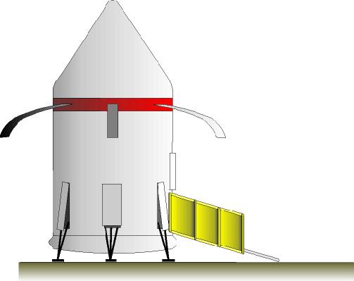
In Flight Sensor Deployment Mast
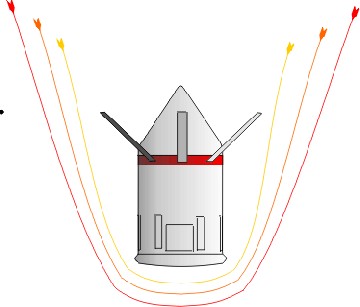
Because of the need for streamlining during re-entry many of the sensors with which are routinely used for survey work are fitted cannot be permanently deployed. The aerials and antennas for such sensors can however be deployed using a mast system housed within the body of the Roton covered by a fairing during high speed flight. Once the speed has dropped to less than 200 km/hr the fairing opens and allows the mast to deploy with the antennae.
A variety of formats are available allowing a range of antenna sizes and constructions to be utilised. The mast is fitted with standard power supply and comms cabling facilitating the attachment of third party equipment. The mast and the elctro-mechanical deployment system is also designed to enable propriety power supply and communications cabling to be used where required.
Optimised Rotor Blade Sets
The blades supplied with each Roton are a general purpose set capable of operation on most inhabited worlds. As a consequence of their adaptability the blades are not as efficient nor is their performance as great as blades designed for any given set of conditions.
Rotor Blade sets optimised to the planetary conditions are available for all core, colony or outpost worlds within the operational parameters of the Roton (atmospheric pressures between 0.8 and 1.2 atmospheres and gravity between 0.8 and 1.2G).
Design Notes
The Roton is a real world reusable launch vehicle. The Rotary Rocket Company have already flown a test version which they plan to develop for a sub orbital flight in 2000. Their version will use a standard rocket engine to reach orbit but will descend on rotor blades.
The original concept for the Roton was proposed by HMX and also used the rotors for lift off as per my 2300 version.
Both the web sites linked to above have a wealth of technical details, and the Rotary Rocket site has videos of test flights, animations of operations etc.. I can recommend both of them.
My 2300AD version of the Roton is an adaptation of the real world designs and is probably less efficient in that it uses liquid hydrogen as fuel (as per the 2300AD standard). One of the real world advantages of the Roton is its use of kerosene. This obviates the need for cryogenic cooling of the fuel and improves the efficiency of the centrifugal pumping.
Version 1.0
07/01/2000
Copyright J.M. Pearson, 2000