|
|
In the 2230s France began to build up to its ambitious colonisation programme. She already had well established colonies on Tirane (2167), Beowolf (2196) and Beta Canum (2205) and was planning four more on Kimanjano (2231), Alderhorst (2244), Aurora (2245) and 61 Ursae Majoris (2248). The Colonial Office realised that the existing arrangements would be completely inadequate when faced with the task of shipping so many colonists up the French Arm. Both the number of vessels and the support infrastructure (maintenance, refuelling, crewing) required were huge.
In 2231 therefore the French Colonial Office initiated a design competition to produce a transport system capable of meeting the needs of the mass emigration along the French Arm. The parameters set were very general but nevertheless extremely testing.
The transportation systems proposed had to meet the following requirements.
The winning design in the Colonial Office competition was a radical departure in ship design which reused a number of proven technologies while combining them with other leading edge equipment.
The Asterie consortium consisted of five major partners, each contributing a major component to the design.
The originator of the Asterie design was Jean Nataniel Eglantier (a distant descendant of the founder of Poire et Fils) who proposed a modular vessel consisting of several parts that could be assembled to suit each particular mission. He was inspired by the european motor/rail sleeper trains of the twentieth century. These trains would depart from their origin in the early evening and drop off wagon-lits (sleeping coaches containing the passengers) and car transporter wagons (containing their motor cars) at stations along the route during the overnight journey. The engine and its remaining coaches and wagons would then arrive at their final destination in the morning. On the return journey, the following night, the process would be reversed with the train gradually gaining coaches and wagons along its route.
Eglantier's proposed vessel had several sections as follows.
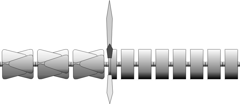
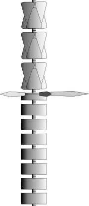
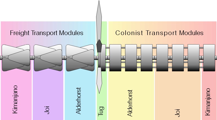
The concept was that the tug would be placed at the centre of the vessel and passenger "coaches" would be docked in sequence on one end of the tug while the freight "wagons" would be docked at the other. At each colony on the route the relevant "coaches" and "wagons" would be detached during the sutterwarp discharge allowing the tug and its remaining load to carry on their journey with no delay. The gradually shortening vessel would complete the circuit of colonies and then return by the reverse route picking up the empty "coaches" as it went.
The use of self contained "coaches" would also allow them to be attached directly to the colony's orbital terminal allowing the colonists to be transferred gradually to the surface. This avoided the need for either large fleets of interface craft or an orbital terminal capable of sustaining large numbers of colonists. An additional benefit of the design was that the "coaches" could also be used as the basis for the accomodation sections of the orbital terminals themselves.
Common to all the parts of the Asterie design were the coupling units used to join the tug to the modules and the modules to one another. To reduce production costs all the coupling units were produced to a common pattern although not all the optional components were fitted to every unit.
The basic unit consisted of a 10m diameter cylinder, 5m in length (divided into two 2.5m long halves). One half of the cylinder was attached to the Aterie module while the outer half was free to rotate around a magnetic ring bearing. The inner section of the unit held a trio of fly wheels (more accurately fly rings) used to store rotational energy to spin or de-spin the outer section. The outer section held docking sensors, three latches spaced equally aroung the periphery alternating with the three latch holes to be used by the mated coupling . Passing through the centre of both sections was the passageway for crew transfer and connectors for data, power and fuel transfer.
The crew transfer passage was simply that - a passage running through the centre of the coupling unit. In docking units attached to uninhabited modules the passage was often simpy blocked with a plate to prevent any debris entering the unit. Where the passage was in use the outer and inner ends would be fitted with standard outer skin doors, which could be operated either locally or remotely, however the passageway remained unpressurised - any airlock systems were constructed within the modules themsleves.
Also common to all the Asterie units were manouvering thrusters placed around the edge of the various components to allow them to be manouvered both individually and as a whole.
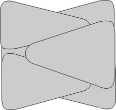
The Asterie tug was based upon one of the largest stutterwarp drives ever to go into regular service and, at the time the largest production drive ever constructed. The 200MW stutterwarp designed by Rouchard was powered by a 200MW Forge des Etoiles Fusion powerplant with a 1MW fuel cell to provide standby power during discharge and maintenance periods.
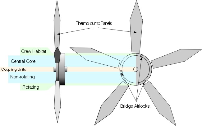
The tug hull consisted of a 35m radius cylinder just 12m long. The bulk of the equipment was sited in a non-rotating central section (30m radius) while the crew living quarters, workstations, monitoring equipment etc. went into the outer 5m thick ring which rotated (at 2.77 rpm) around the central core to provide a 0.3G spin habitat.
Five large thermo-dump panels were mounted on the outer radius of the central, non-rotating, section and protruded radially beyond the spin habitat. The fusion reactor required four of the panels to operate at full efficiency, the fifth panel was present as a hot spare.
At either end of the central hull section a standard Asterie coupling unit was placed allowing the tug to be connected to other Asterie modules at both ends. The crew was only capable of operating the tug vessel, all engineering or maintenance required by any attached modules had to be provided within the module itself.
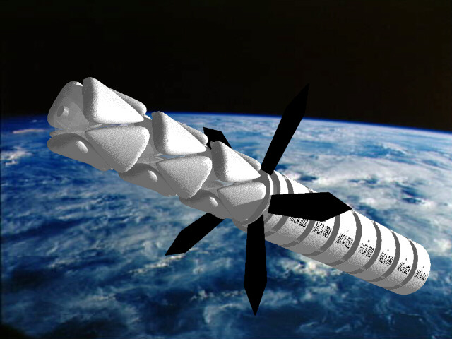
When viewed end on, with the thermo-dump panels in the correct orientation, the Asterie tug had the appearance of the starfish (a central circular body with five arms) from which it derived its name.
Both the central section and habitat were independantly pressurised and two de-spin capsules (running on circular tracks around the core just below the habitat ring) were provided to give the crew access to the central section.
The capsules were normally parked on the central section and when required would run around the tracks until they matched the rotation of the habitat ring, they would then mate with an airlock in the ceiling (underside) of the ring to allow crew transfer. Once the crew were aboard the capsule would slow and finally come to rest over an airlock in the central section allowing the crew access. The central section also had an airlock at the centre of either end which connected to the coupling unit passageways.
In addition to the two ceiling (inner wall of the ring) airlocks the habitat ring also had three airlocks evenly spaced around the end wall facing away from the thermo-dump panels. These airlocks could be connected to the matching airlocks in an adjacent Colonist Module once the spins of the habitat ring and module had been matched. The bridge airlocks, as they were known, allowed access from module to module along the who habiatble length of the ship.
The crew consisted of 14 bridge, 30 engineering and one medical officer.
All the Asterie tugs were named after schooling sea creatures. The names and commisioning dates of the seven vessels were as follows.
| Vessel | Laid Down | Commissioned |
| Le Dauphin (Fr : Dolphin) | 2235 | 2239 |
| Le Marsouin (Fr : Porpoise) | 2237 | 2240 |
| L' Aiglefin (Fr : Haddock) | 2239 | 2241 |
| Le Hareng (Fr : Herring) | 2241 | 2243 |
| La Sardine | 2242 | 2244 |
| Le Thon (Fr : Tuna) | 2243 | 2245 |
| La Morue (Fr : Cod) | 2244 | 2246 |
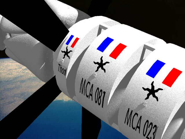
The Colonist Transport Module (the "wagon-lit" - sleeping coach - of the original concept) was derived from the design of numerous low G space station habitats. Each of the modules, produced by L5 Construction, was basically a simple closed end cylinder with a radius of 35m and a length of 30m. In the centre of each end cap was the 10m diameter Asterie coupling unit giving the whole module the appearance of a large, solid wheel with a short axle through the centre.
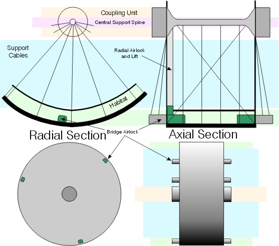
Inside the cylinder however the arrangements were considerably more complex. Making up a 6m thick cylinder wall was the accommodation and life support for 1,000 colonists and 100 support personnel. Along the axis of the cylinder was a 2m diameter tower which acted as an anchor for the radial support struts and cables, a load bearing member for axial loads on the docking units and a location for the fuel cells, their fuel and the hydroponic farm sun lamps.
The habitat section consisted of two decks. The main deck of the module was the outermost while all the ancillary equipment was placed between the decks to give the maximum possible area at the highest gravity (and allow maintenance access from both sides). The upper deck of the cylinder (with the utility space as the floor and a ceiling of transparent membrane) was primarily occupied by the hydroponic farm / life support system designed by BioSystem. The two floors were supported by cables attached to the axial tower so that structurally each was an endless suspension bridge.
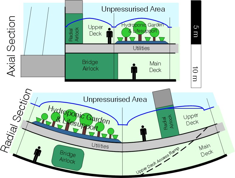
The BioSystem designed life support system was effectively a self contained ecosystem capable of replacing the carbon dioxide breathed out by the colonists with oxygen and processing the colonists other waste products by growing food crops. The system could operate in two distinct modes the first (known as summer) was capable of supporting 1100 personel while the second (winter) had a massively reduced productivity and was used during the return journey when only a minimum number of maintenance staff were present. The system was switched between modes by varying the strength and period of illumination and adjusting the chemical composition of the water supply. The switch over between modes would take several days (periods known as autumn and spring).
The habitat main deck had three "bridge" airlocks evenly spaced around both end walls which could be connected to the matching airlocks in the adjacent Colonist modules (or tug) once the spins of the modules had been matched (in the same way that passenger coaches are linked on railway trains). In addition there were also two airlocks giving access to the unpressurised core of the cylinder, one against each end wall, which were connected by unpressurised lifts to the coupling unit access passageways.
Unlike conventional spacecraft (which normally have a non rotating core) the whole of the cylinder rotated at 2.77 rpm giving a pseudo gravity of 0.3G to the module's main deck - sufficient to prevent significant muscle and bone wastage among the colonists with a low enough rotational period and large enough radius to avoid motion sickness. The coupling units at either end could counter-rotate (independantly) so that they were at rest relative to external objects allowing docking with other modules, the tug, orbital terminals or other vessels.
The vast majority of the freight carried by the Asterie class was contained in single use lifting body re-entry vehicles. Each vehicle, known as a Vairon (Fr : Minnow), was 60m long, up to 45m wide and 18m deep and had a cargo volume of 16,000 m3 and a mass limit of 10,000 tonnes. The empty lifting body weighed 500 tonnes bringing the mass of a loaded Vairon to 10,500 tonnes. The support frame itself had a 200 tonne mass plus 275 tonnes for the two coupling units bringing the total mass of a fully loaded Freight Module to 63,475 tonnes.
The Vairon lifting body was literally only that - an aerodynamic shell, two dorsal stabiliser fins and an ablative heat shield built around the cargo bay. The Vairons had no propulsion, crew accomodation or power supply, the only equipment they utilised was a minimal automatic temperature control mechanism used to maintain the cargo within an acceptable temperature range (the cargos were normally stored in a low pressure nitrogen atmosphere to avoid problems with exposure to vacuum).
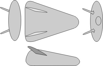
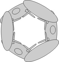
The Vairons were transported in groups of six arranged alternately head-to-toe around a 60m long hexagonal frame to which they were secured via dorsal attachment points (so that the Vairon's ablative belly faced outwards and the stabiliser fins inwards). Power was supplied from the tug via an umbilical connector located midway between the fins. The whole cargo module (support frame plus six Vairons) was spun at 1 rpm to equalise solar heating during stutterwarp discharge.
 |
 |
The support frame was fitted with a standard Asterie coupling unit at either end so that Freight Transport Modules could be atttached to each other and to the tug unit.
In effect any object which could have an Asterie coupling unit attached to either end along the centre of gravity could be transported. The actual examples are too numerous to mention however some of the more common modules are listed below.
| Statistic | Value | Units | Notes | Mass | Volume | Cost |
| Power Plant | 200 | MW | Fusion | 6500 | 6500 | 100 |
| Power Plant | 1.0 | MW | Fuel Cell | 35 | 35 | 10 |
| Fuel | 30 | Days | Fuel Cell | 530.36 | 321.43 | |
| Stutterwarp | 200 | MW | 77 | 58 | 17.4 | |
| Crew Workstation | 7 | Bridge | 35 | 56 | ||
| Crew Workstation | 15 | Engineering | 75 | 120 | ||
| Crew Workstation | 1 | Medical | 5 | 8 | ||
| Sensor | Nav & DSS | 20 | 21 | 0.12 | ||
| Accomodation | 45 | Crew | Comfort 3 | 787.5 | 3375 | |
| Spin Macinery | 33.75 | 33.75 | ||||
| Life Support | 45*150 | Days | 6.75 | 33.75 | ||
| Hull | 35 | m | Diameter Cylinder | 49.22 | 167.84 | 0.74 |
| Totals | 8121.43 | 10769.86 | 128.26 |
| Statistic | Value | Units | Notes | Mass | Volume | Cost |
| Power Plant | 3*0.4 | MW | Fuel Cell | 39 | 39 | 9 |
| Fuel | 150 | Days | Fuel Cells | 1285.71 | 2121.43 | |
| Stutterwarp | None | |||||
| Crew Workstation | 40 | 200 | 320 | |||
| Sensor | None | |||||
| Accomodation | 1100 | Crew | Comfort 0 | 13750 | 27500 | |
| Spin Macinery | 275 | 275 | ||||
| Life Support | 1100*150 | Days | 165 | 825 | ||
| Hull | 35 | m | Diameter Cylinder | 523.70 | 130.92 | 1.96 |
| Totals | 16238.41 | 10.96 |
| Statistic | Value | Units | Notes | Mass | Volume | Cost |
| Power Plant | None | |||||
| Stutterwarp | None | |||||
| Load | 2, 3, 4 or 6 | Vairon | Interface Vehicles | |||
| Cargo | 60,000 | tonnes | 10,000 tonnes per Vairon | 63000 | ||
| Support Frame | 200 | |||||
| Sensor | None | |||||
| Accomodation | None | |||||
| Spin Macinery | 2 | Coupling units | 275 | |||
| Totals | 63475 |
| Asterie Stutterwarp Efficiency |
|
|||||||||||||||
| 0 | 1 | 2 | 3 | 4 | 5 | 6 | 7 | 8 | 9 | 10 | 11 | 12 | 13 | 14 | ||
|
Freight Modules |
0 | 4.22 | 2.93 | 2.47 | 2.21 | 2.03 | 1.90 | 1.79 | 1.71 | 1.64 | 1.58 | 1.53 | 1.48 | 1.44 | 1.41 | 1.37 |
| 1 | 2.04 | 1.91 | 1.80 | 1.72 | 1.65 | 1.59 | 1.53 | 1.49 | 1.45 | 1.41 | 1.38 | 1.35 | 1.32 | 1.29 | 1.27 | |
| 2 | 1.65 | 1.59 | 1.54 | 1.49 | 1.45 | 1.41 | 1.38 | 1.35 | 1.32 | 1.29 | 1.27 | 1.25 | 1.23 | 1.21 | 1.19 | |
| 3 | 1.46 | 1.42 | 1.38 | 1.35 | 1.33 | 1.30 | 1.27 | 1.25 | 1.23 | 1.21 | 1.19 | 1.18 | 1.16 | 1.14 | 1.13 | |
| 4 | 1.33 | 1.30 | 1.28 | 1.25 | 1.23 | 1.21 | 1.19 | 1.18 | 1.16 | 1.14 | 1.13 | 1.12 | 1.10 | 1.09 | 1.08 | |
| 5 | 1.23 | 1.21 | 1.19 | 1.18 | 1.16 | 1.14 | 1.13 | 1.12 | 1.10 | 1.09 | 1.08 | 1.07 | 1.05 | 1.04 | 1.03 | |
| 6 | 1.16 | 1.15 | 1.13 | 1.12 | 1.10 | 1.09 | 1.08 | 1.07 | 1.06 | 1.04 | 1.03 | 1.02 | 1.01 | 1.01 | 0.99 | |
| 7 | 1.10 | 1.09 | 1.08 | 1.07 | 1.06 | 1.05 | 1.04 | 1.03 | 1.02 | 1.01 | 1.00 | 0.99 | 0.98 | 0.97 | 0.96 | |
| 8 | 1.06 | 1.05 | 1.04 | 1.03 | 1.02 | 1.01 | 1.00 | 0.99 | 0.98 | 0.97 | 0.97 | 0.96 | 0.95 | 0.94 | 0.94 | |
| 9 | 1.02 | 1.01 | 1.00 | 0.99 | 0.98 | 0.98 | 0.97 | 0.96 | 0.95 | 0.94 | 0.94 | 0.93 | 0.92 | 0.92 | 0.91 | |
| 10 | 0.98 | 0.98 | 0.97 | 0.96 | 0.95 | 0.95 | 0.94 | 0.93 | 0.93 | 0.92 | 0.91 | 0.91 | 0.90 | 0.89 | 0.89 | |
| 11 | 0.95 | 0.95 | 0.94 | 0.93 | 0.93 | 0.92 | 0.91 | 0.91 | 0.90 | 0.90 | 0.89 | 0.88 | 0.88 | 0.87 | 0.87 | |
| 12 | 0.93 | 0.92 | 0.91 | 0.91 | 0.90 | 0.90 | 0.89 | 0.89 | 0.88 | 0.87 | 0.87 | 0.86 | 0.86 | 0.85 | 0.85 | |
| 13 | 0.90 | 0.90 | 0.89 | 0.89 | 0.88 | 0.87 | 0.87 | 0.86 | 0.86 | 0.86 | 0.85 | 0.85 | 0.84 | 0.84 | 0.83 | |
| 14 | 0.88 | 0.88 | 0.87 | 0.87 | 0.86 | 0.86 | 0.85 | 0.85 | 0.84 | 0.84 | 0.83 | 0.83 | 0.82 | 0.82 | 0.82 | |
In order to maintain the flow of colonists and cargo along the French Arm five Asterie vessels (each typically leaving Earth with seven Colonist Modules and three Freight Modules) were required to operate at full capacity. Each tug would make three trips per year either on the Kimanjano / Joi / Alderhorst run or the Kimanjano / Aurora run, both of which required just less than 120 days for the round trip (the exact timings depended upon the load carried by the Asterie and the order in which the modules were unloaded).
This very tight schedule left almost no time for maintenance between runs consquently a fleet of seven tug vessels was required to allow sufficient time to maintain the vessels. On average each tug had a major maintenance period after every four trips (3 months every 15 months - an 80% availability).
The maintenance of the Colonist Modules was much less problematic as they were effectively unused for up to 50% of their lives, while awaiting collection for and during the return journey. All but the most major maintenance could therefore be carried out by the modules' crews during the return journey. The large pool of modules also made removing them for major overhauls relatively easy to schedule.
Freight for the colonies was delivered to the Gare des Etoiles (Fr : Star Station) via catapult or interface vehicle from Earth or orbital transfer from other space stations. Once each load was assembled a Vairon lifting body was constructed around it and the Vairons were then grouped together on Asterie support frames on a single colony basis. If less than six Vairons were available for a given colony the design of the Asterie Freight Modules meant that a single support frame could hold two, three or four Vairons without any loss of stability. Once each Freight Transport Module was completed it was spun up to the standard 1 rpm and transferred by OTV to a nearby parking orbit.
While the Freight Modules were being assembled the colonists, their baggage and consumables were also being brought to the Gare des Etoiles by interface vehicles. Once aboard the Gare the colonists were quickly transferred to spinning Asterie Transport Modules which were docked to the station and connected by the bridge airlocks. This procedure meant that the only time colonists were subjected to zero gravity was in the spaceplane between attaining orbit and docking with the station. This arrangement greatly reduced the problems of coping with thousands of untrained, space sick colonists.
As each Colonist Transport Module received its full complement it was detached from the station and moved by an OTV to a nearby parking orbit where it was docked with any waiting Colonist Modules. Once docking was successfully completed the spin of the new module was matched to that of the existing modules and finally connected to the adjacent module by bridge airlocks. The Colonist Modules were assembled in order of destination so that all the modules for any one colony were together and those for the nearest colony were at one end of the chain while those for the farthest colony were at the other.
Once both cargo and passengers were finally assembled the Asterie tug was docked with the end Colonist Module from the farthest colony adjacent to the crew habitat ring. The spins of the habitat ring and Colonist Modules were then matched to allow the crew habitat to be attached to the adjacent module. One this process was complete the Freight Modules were attached to the tug's other coupling unit in order of their destination so that all the modules for any one colony were together and those for the nearest colony were at the loose end of the chain while those for the farthest colony were attached directly to the tug.
The completed Asterie vessel therefore consisted of a chain of Freight Modules attached to one end of the tug and a chain of Colonist Modules attached to the other (typically seven Colonist and three Freight Modules). The construction was arranged such that the rotation of the Freight and Colonist Modules was in the opposite direction so that the overall rotational energy of the vessel was minimised enabling the whole vessel to be spun down in emergencies by use of the coupling unit spin mechanisms.
Once the vessel was completed, and final checks caried out,
the tug would engage its stutterwarp drive and head off for the
stars. 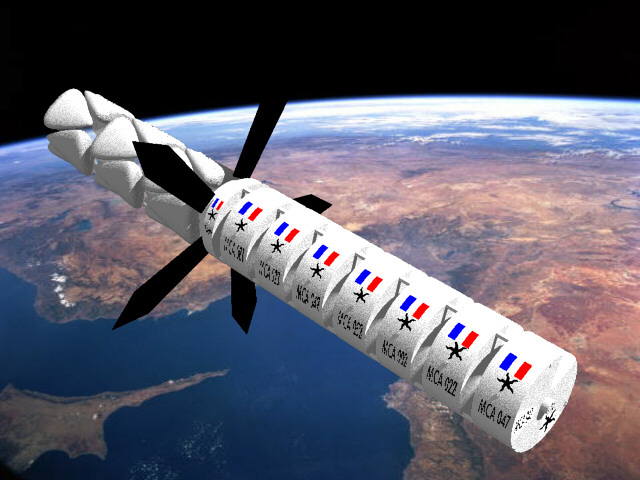
During flight a typically loaded Asterie could be home to nearly 8,000 souls. Although each Colonist Module was designed to accomodate 1,000 colonists and 100 support staff the majority of the supporting personnel were themselves colonists - albeit colonists with particular skills or additional training.
Each module required engineering staff to manage the fuel cells and maintain the life support system. A permanent crew of ten (split into three shifts of three plus a Chef de la Module) was responsible for the module's systems. During the wait prior to the outward journey a number of suitably qualified colonists would receive additional training to assist in the life support maintenance. Medical, security and educational services were provided by the colonists themselves with great care being taken to ensure that the correct balance of skills and proffessions was present in each module.
With journey times of up to sixty days, plus additonal time awaiting collection by the Asterie in Earth orbit and interface transport in orbit around the colony, colonists could be living in a Colonist Module for up to three months
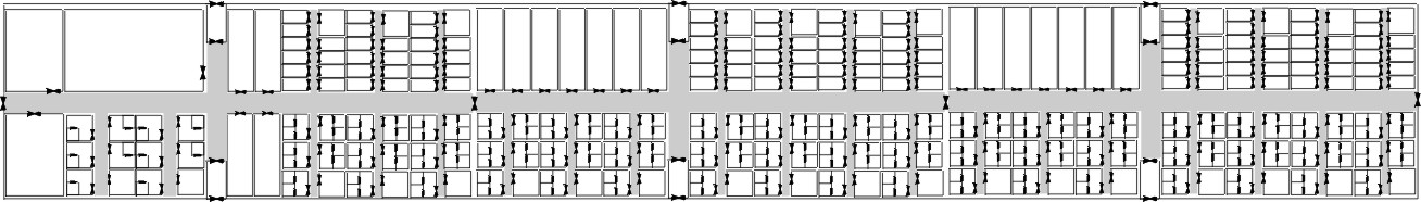
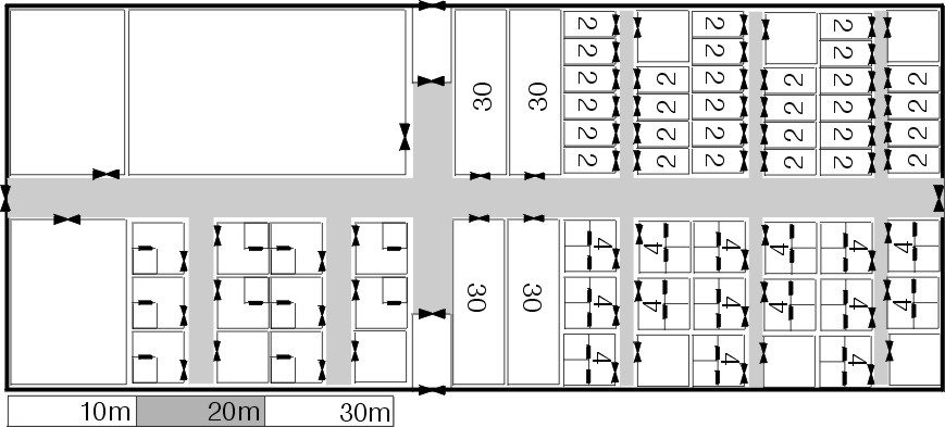
To accomodate the colonists and crew the main deck had a floor space of nearly 6,600 square metres (30m by 220m) which was split into thirds, by airtight bulkheads (so that each segment was capable of operating independently of the others for short durations in an emergency). Two of the segments had common floor plans providing accomodation for 430 in either four person family rooms, double rooms or 30 person dormitories.
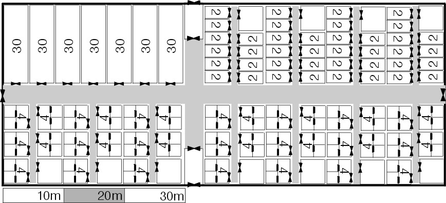
The third segment had accomodation for 240 (bringing the total to 1100 at a comfort level of zero) plus crew work areas and communal dining and activity areas.
This arrangement, coupled with the less than full occupancy, allowed sufficient flexibility to accomodate the varying loads of colonists (families, couples and singles) and provide additional space to increase the comfort levels for the permanent crew. The cabins were all fitted with furniture allowing them to be quickly and eaily converted from living space into sleeping space (foldaway beds, inflatable seats, suspended tables etc.).
The life support system occupying the upper deck also provided additional space for crew and colonists alike. The deck had a number of open areas and access routes that could be used for leisure and exercise and proved very popular. The garden gave the impression of much more open and outdoors and was a welcome relief to relatively cramped and confined quarters on the lower deck.
During the journey the colonists were involved in a full time education programme providing them with the knowledge and skills they would require on their new worlds. These programmes were normally begun on Earth and were designed so that the more practical aspects were covered before embarcation with the more theoretical aspects (suitable for study in with the more restricted facilities available aboard) covered during the journey. The colonists would engage in accademic studies, simulated exercises and detailed planning for their colonial careers. Where possible a number of the colonists would be capable of teaching, or at least advising on, the subjects being studied by their fellows. For instance medical staff would teach first aid, qualified technicians the basics of their expertise etc. The Colonist Modules were equipped with comprehensive educational facilities (computer libraries, a range of virtual reality simulators, display equipment, computer moderated examination systems etc.).
All the training and education could of course have been carried out before transportation however the programmes gave the colonists an occupation during their long journey to the stars.
As the vessel reached each colony on its itinery it would enter orbit around the colony world nearby the orbital terminal. As the stutterwarp was discharged the Freight and Colonist Modules destined for that colony would be undocked from either end of the vessel by an OTV. The Freight Modules would be moved to a parking orbit while the Colonist Modules would be docked and linked with the orbital terminal (which was itself often partially constructed from standard Asterie Colonist Modules) via the bridge airlocks.
Once the drive was fully discharged the shortened vessel would depart for the next destination leaving the Colonists and Freight to be unloaded at leisure.
The colonists were transferred to their final destination on the planet's surface by a regular interface service. As the onward journey of the vessel was not delayed by interface transport or orbital terminal accomodation bottlenecks a lower capacity service was used to gradually ferry down the new arrivals. This method also had the advantage of putting less strain on the planet-side reception and transport facilities. Once the Colonist Modules were emptied they were moved by OTV to a parking orbit to await collection by the next returning Asterie tug.
The Vairon lifting bodies, still mounted in their spinning support frame, were fitted with dorsally mounted autopilot and maneouvering thruster units while in orbit. Each Freight Module was then de-orbitted by an Asterie coupling unit equipped OTV which would release the Vairons with the minimum relative (to the planetary surface) velocity to reduce re-entry heating as far as possible. The six Varions were released from the support frame by the simple expedient of opening the docking grapples, the unrestrained Vairons would then drift apart and orient themselves for re-entry. The frames remained attached to the OTV and were returned to orbit to await collection by the next returning Asterie tug.
The Vairon autopilots would land their charges (using GPS) in the designated landing zone, which was normally coastal waters or a large inland lake. The Vairons would then be retrieved by boats and towed to port for unloading and scrapping. Only the autopilots and thruster units would be returned to orbit by interface vehicle for reuse on the next batch of Vairons.
At the final colony on the route the remaining modules would
be undocked and the empty Colonist Modules from the previous Asterie
reconnected. Once the exchange was made the Asterie would retrace
its route picking up empty Colonist Modules and the empty freight
support frames on the way back to Earth. 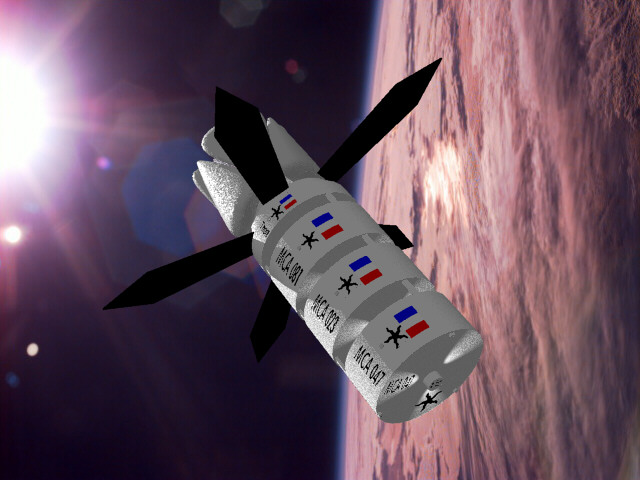
As fusion powered vessels the Asteries required no fuelling facilities along their chosen routes - the primary reason for the choice of the fusion power plant. Where significant support was required was in the transfer of colonists from the Earth's surface to the Asterie in Earth orbit and from the Asterie in orbit around the colony world to the planet's surface.
The Gare des Etoiles was France's main terminal in low earth orbit (LEO) the early 2200s through which the vast majority of her passanger traffic passed. With the steady growth in orbital, in-system and interstellar traffic in the 2210s and 2220s the Gare's facilities were begining to become over stretched and a replacement station was constructed in the early 2230s. Rather than demolish the Gare des Etoiles it was gradually refurbished to handle the large increase in transient colonists and the major maintenance and assembly requirements of the Asterie Colonist and Freight Modules.
The Asterie tugs were constructed and maintained at the L5 shipyards where all the specialist facilities (fusion engineering, stutterwarp calibration etc.) were available.
The orbital terminal at Kimanjano was constructed before the Asterie system came into service and was of a typical, pre Asterie, modular design. The terminal was latter modified to provide a standard docking port for the Asterie Colonist Modules connected to a shuttle docking port capable of loading passangers under spin.
The Joi, Alderhorst and Aurora terminals however were primarily constructed from the Asterie components that were delivered as part of the initial colonial build up. Several specially modified Colonist Modules were connected directly together (once the colonists were unloaded and with the coupling units removed) to form the main habitation cylinder for the terminal. As the terminal expanded a second cylinder was created in the same manner. The main structural members for the terminal were formed from Vairon support frames, again connected directly together once the Vairons had been de-orbited and the coupling units removed (for return to Earth).
These standard Asterie components were modified for their new purpose. For instance the internal fittings of the Colonist Modules were reworked to provide much larger communal spaces while personnel transit systems (effectively pressurised lifts) were fitted within the support frames. In addition specialist units were also added (such as the Asterie / Interface docking port, solar power receivers, fuel cracking and storage facilities) as required.
The core of the docking port was a 70m diameter cylinder rotating within a 90m outer diameter ring containing the spin mechanism and despin capsules to link the port to the zero gravity section of the terminal. One end of the rotating cylinder was equipped with a standard Asterie coupling unit and three bridge airlocks to allow it to connect to a Colonist Module and allow the transfer of colonists under spin gravity.
The other end of the cylinder was open to space allowing an interface vehicle to enter along the cylinder's axis. The interface vehicle would first align itself with the central axis of the docking port and spin around its axis at 2.77 rpm to match the spin of the port. The vehicle would then enter the port, with its landing gear extended, and dock with a landing frame. The landing frame and attached vehicle would then be moved radially outwards towards the cylinder wall (landing gear outermost), thereby gradually increasing the spin gravity experienced by the vehicle. To balance the changes in angular momentum a liquid ballast system pumped mass from around the outer radius of the cylinder to to the point on the radius opposite the interface vehicle. A system of flywheels was also used to maintain the spin of the docking port at 2.77 rpm (moving the mass of the vehicle from the axis to the outer radius would otherwise reduce the spin of the port).
Once the interface vehicle had been "lowered" to the outer radius of the docking port (now resting on its landing gear) the vehicle airlocks were connected to the pressurised area of the docking port. The colonists were then able to easily board without having to leave the pressurised, spin gravity region of the port. Once the colonists had boarded the vehicle was "raised" back to the port's central axis (and zero gravity), released from the support frame and launched back into space. The docking port's ballast and flywheel systems operating in reverse to accomodate the changes in angular momentum.
The inspiration for the Asterie design was the motor/rail concept descibed above. I was also thinking that large colonial transports would be too valuable to leave hanging around in orbit while you spent weeks unloading all the colonists and cargo. The alternative would be to either have a large fleet of interface vehicles (stated to be the most expensive component of interstellar travel) which would remain idle for much of the time or orbital terminals capable of housing large numbers of transients.
The Asterie system means that there is only a limited duplication of life support facilities for the colonists, the number of interface vehicles at each colony is minimised and the utilisation of the most expensive component (the stutterwarp and power plant) is maximised.
I also thought that the "train" concept would be interesting from the scenario point of view - murder on the Alderhorst Express anyone? Also the departure from the usual naval metaphor makes life a little more varied.
Many thanks to Terry Kuchta for pointing out some of the errors in the original design calculations, which are hopefully now all corrected.
The images were produced in Corel Dream 3D and use NASA photos as backdrops.
Version 1.1
11/06/2001
Copyright J.M. Pearson, 2001
Photographs used as backgrounds in images are copyrigt NASA